Skip to content
 Since the Industrial Revolution, the automotive industry has flourished. However, traditional internal combustion engine vehicles have also imposed significant environmental impacts through their emissions. In 2021, transportation accounted for 10.4% of total societal carbon emissions. Green development has become a global consensus, with 197 countries signing the Glasgow Climate Pact to date, and 138 countries committing to net-zero emissions targets. These efforts reflect the urgent need for more sustainable practices across industries, especially in the transportation sector.
The strategy of “Electrification of Energy, Greening of Electricity” is pivotal for achieving carbon neutrality. This global effort seeks to reduce dependency on fossil fuels, shifting to renewable energy sources and electric vehicles (EVs) for cleaner energy use. Consequently, advancing new energy vehicles (NEVs) is not only essential for China’s transition from a major automotive player to an automotive leader but also a strategic measure to address climate change and drive sustainable development. The shift to NEVs represents an opportunity to reduce emissions, enhance energy efficiency, and foster economic growth through innovation in green technology.
Batteries serve as the power source for electric vehicles (EVs). Their capacity and energy density directly impact driving range, while their quality metrics critically influence safety performance. Key technical challenges for EVs include:
- Preventing battery overcharging and over-discharging during operation;
- Mitigating cell imbalance within battery packs;
- Enhancing battery pack efficiency;
- Extending service life.
The development of high-performance batteries, combined with sophisticated battery management systems, is crucial to overcoming these challenges. Efficient, safe, and long-lasting batteries are essential to the widespread adoption of electric vehicles and the transition to green transportation.
As the critical nexus between EV battery packs, vehicle systems, and electric motors, the Battery Management System (BMS) utilizes integrated sensors to perform real-time monitoring of battery voltage, current, and temperature. This enables comprehensive management of the vehicle’s electric powertrain, ensuring optimal operation and safety. With the constant evolution of battery technology, the BMS also adapts, playing an increasingly significant role in ensuring the longevity and performance of electric vehicles.
In summary, functioning as the core control unit of the battery system, the BMS plays a vital role in electric vehicles. Research on core BMS technologies holds significant value for the industry’s advancement, particularly in enhancing efficiency, safety, and sustainability in the growing electric vehicle market.
1.Functional Modules of BMS

Figure 1: BMS Functional Overview
The BMS serves as the central control unit of the power battery system, responsible for managing, maintaining, and monitoring all battery modules. It is tasked with:
- Safety protection;
- Enhancing energy utilization efficiency;
- Extending battery service life;
- Ensuring reliable battery operation.
The core functions of BMS include:
- Thermal management and safety protection;
- Real-time monitoring of physical parameters (voltage, current, temperature);
- Battery state estimation (SOC/SOH/SOP);
- Online diagnostics and early warning;
- Charge/discharge control and cell balancing.
These functions work together to ensure the safe, efficient, and reliable operation of electric vehicle batteries. By constantly monitoring critical metrics and adjusting parameters, the BMS ensures that the battery operates within safe limits and delivers optimal performance over its lifespan.
2.Enabling Technologies for Core Functions
2.1 Battery Monitoring
For a BMS to deliver its functions, it must first acquire physical parameters such as voltage, current, and temperature from the battery. These parameters are essential for understanding the battery’s status, predicting performance, and ensuring its safety during operation.
2.1.1 Voltage Monitoring
Electric vehicle (EV) batteries consist of several thousand individual cells connected in parallel and series configurations to meet the vehicle’s voltage and capacity requirements. Consequently, the state variations of each cell directly impact the overall pack performance. Proper voltage monitoring is critical to avoid overcharging or deep discharging, which can damage the cells.
Voltage serves as a critical parameter reflecting battery operating status, making real-time voltage monitoring essential. By closely monitoring the voltage of each individual cell, the BMS can maintain the overall health of the battery pack, avoiding dangerous over-voltage or under-voltage conditions.
As mandated by the GB/T 38661-2020 standard (Technical Specifications for Battery Management Systems of Electric Vehicles), specific requirements for voltage measurement accuracy are defined, as illustrated in Figure 2:

Figure 2: Voltage Monitoring Requirements per GB/T 38661-2020
The BMS primarily utilizes dedicated battery voltage monitor ICs to acquire and measure voltages across multiple individual cells, specifically known as AFE (Analog Front End) chips. Major suppliers dominating the market include ADI, ST, TI, and NXP.
Taking ADI’s LTC6811 as a representative product, Figure 3 shows its recommended sampling circuit:

Figure 3: Recommended Sampling Circuit for LTC6811
The battery cells are connected in series by stacking them sequentially. The sampling chip is connected to the batteries as shown in the diagram, and forms an RC filter circuit with a 100Ω series resistor and a 10nF capacitor to sample the voltage.
Since the chip processes digital signals while the sampled signal is analog, the LTC uses an ADC (Analog-to-Digital Converter) to convert the sampled analog signal into a digital signal for processing, storage, and display. This conversion process ensures that the BMS can operate on accurate, real-time data, essential for efficient battery management.
2.1.2 Temperature Monitoring
Temperature has the most significant impact on battery performance, manifested in battery capacity, voltage, and service life. At lower temperatures, internal resistance increases and chemical reaction rates slow, reducing power and energy output. At higher temperatures, reaction rates intensify, but elevated temperatures disrupt chemical equilibrium, shortening battery lifespan.
Typically, lithium-ion batteries operate optimally between 15°C to 35°C, while electric vehicles function in -30°C to 50°C environments. Thus, thermal management (heating/cooling) based on battery temperature is essential. Precise temperature monitoring is therefore critical to ensure the safety and efficiency of EV batteries.
GB/T 38661-2020 specifies the following requirements for temperature monitoring accuracy:

Figure 4: Temperature Monitoring Requirements in GB/T 38661-2020
The temperature sampling circuit for batteries typically measures the resistance of external NTC resistors via the ECU, then converts it into temperature values based on the R-T curve.
NTC temperature sensors are primarily fabricated from metal oxides such as Mn and Cu through ceramic and semiconductor processes. Their operating principle is:
At lower temperatures, fewer charge carriers in the composite material result in higher resistance. As temperature rises, increased charge carriers reduce resistance accordingly. The R-T curve is shown in Figure 5.

Figure 5: R-T Curve Characteristics of Thermistors with Different Temperature Coefficients
Figure 5 shows that the R-T curve exhibits a non-linear relationship: resistance changes steeply at low temperatures and gently at high temperatures, leading to significant measurement errors. Therefore, a transistor is incorporated into the working circuit to achieve higher-precision measurements. The operational circuit is illustrated in Figure 6.

Figure 6: Temperature Sampling Schematic Circuit
At low temperatures, the sensor’s high resistance value activates only the 10kΩ path with the transistor in cut-off. The measured value remains accurate as the sensor resistance approximates 10kΩ.
At high temperatures, reduced sensor resistance (significantly below 10kΩ) triggers the ECU to switch on the transistor. This connects the 1kΩ resistor in series with the transistor, forming a parallel circuit with the 10kΩ resistor grounded through the sensor. The effective resistance then approaches 1kΩ, maintaining measurement accuracy despite temperature rise.
2.1.3 Current Monitoring
The charging and discharging power of automotive traction batteries is exceptionally high. During BMS operation, the aggregate current is a critically monitored parameter. Current detection serves as the primary safeguard against short circuits and overcurrent faults.
Unlike voltage or temperature monitoring:
- Quantitatively: Only the aggregate current requires monitoring across the entire battery system
- Frequency: Current sampling occurs at high frequencies to meet SOC (State of Charge) estimation requirements
GB/T 38661-2020 specifies the following current monitoring accuracy criteria:

Figure 7: Current Monitoring Requirements in GB/T 38661-2020
Two current monitoring approaches are implemented in BMS:
Current Sensor-Based
Utilizes either Hall-effect sensors or fluxgate sensors.
Shunt Resistor-Based
Measures current via fundamental voltage-current relationships.
2.1.3.1 Shunt Resistor Approach
The shunt resistor approach involves connecting a shunt resistor in series within the battery circuit. Current is calculated via Ohm’s Law by measuring the voltage drop across the resistor, as shown in the schematic below:

Figure 8: Schematic Diagram of Current Measurement via Shunt Resistor
The shunt resistor features extremely low resistance, with mainstream specifications of 0.1mΩ or 0.15mΩ. Given typical EV operating currents of 500A, the resulting voltage drop remains below 50mV, necessitating integration with an amplifier circuit.电路使用。
2.1.3.2 Current Sensor Solution
The sensor solution comprises Hall-effect sensors and fluxgate sensors, both employing indirect measurement methods. The schematic diagram of a Hall-effect current sensor is shown below:

Figure 9: Schematic Diagram of Hall-Effect Current Sensor
The Hall-effect current sensor operates on the Hall effect principle: When current flows through the primary conductor, it generates magnetic flux in the core. Within the core’s air gap, Lorentz force deflects charge carriers in the Hall element, creating charge accumulation that forms a transverse electric field. This produces a millivolt-level voltage proportional to the primary current, which is converted via operational amplifiers into a secondary current for primary current calculation.
The fluxgate current sensor measures current by exploiting the nonlinear relationship between magnetic flux density and field strength in a high-permeability ferromagnetic core under AC saturation excitation, as illustrated in the following schematic:

Figure 10: Schematic Diagram of Fluxgate Current Sensor
The fluxgate current sensor operates by generating a fixed high-frequency AC square wave from its chip, driving the core into alternating saturation. When measured current is zero, the detection coil outputs an induced EMF containing only odd harmonics of the excitation waveform, exhibiting symmetrical positive/negative peaks (see upper-right waveform in Figure 10). With non-zero measured current, the resulting magnetic field superimposes onto or counters the excitation field. Superposition causes premature core saturation, while counteraction delays saturation, biasing the secondary induced current (see lower-right waveform in Figure 10). This amplitude deviation correlates proportionally with measured current, enabling current calculation.
The predominant current sensing solutions exhibit distinct advantages and limitations:
Shunt Resistor
- Advantages: High accuracy, low temperature drift, cost-effectiveness, high output frequency
- Limitations:
- Heat dissipation – At 500A, ≈25W power loss requires robust thermal management
- Isolation requirements – Series connection in main circuit necessitates isolation components for LV/CAN circuits, increasing cost
Hall-Effect Sensor
- Advantages: Low cost, fast response, simple circuitry
- Limitations:
- Non-linear input-output characteristics reduce accuracy (especially in low-current measurements)
Fluxgate Sensor
- Advantages: High current capacity, minimal temperature sensitivity, low heat generation, superior accuracy (supports BMS protection and SOC calculation)
- Limitations:
- Vulnerable to external magnetic interference (requires EMI mitigation design)
The characteristics are summarized in the table below:

2.2 Battery State Analysis
SOC (State of Charge) and SOH (State of Health) constitute two critical parameters in battery systems, providing references for safety protection, charge/discharge control, and thermal management. Accurate real-time acquisition of SOC/SOH data is therefore essential for extending battery lifespan and ensuring operational safety. However, as intrinsic battery parameters, SOC and particularly SOH cannot be measured directly or precisely, and must instead be estimated through processing the battery’s electrical characteristics.
2.2.1 SOC Estimation
SOC reflects the percentage of a battery’s currently available capacity relative to its maximum available capacity, calculated as:

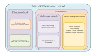
SOC refers to the commonly termed remaining capacity. Its estimation methods primarily include direct and indirect approaches, as detailed in the diagram below:

Figure 12: Battery SOC Estimation Methods
2.2.1.1 Coulomb Counting Method
The Coulomb counting method estimates SOC by integrating measured current over time during charge/discharge cycles, calculated as follows:

Where:
- t0t0 denotes initial time
- tk=t0+k⋅Δttk=t0+k⋅Δt, with ΔtΔt as sampling interval
- SOCkSOCk and SOC0SOC0 represent SOC values at tktk and t0t0 respectively
- ηη indicates Coulombic efficiency
- Ik−1Ik−1 is current at k−1k−1 sampling instance
For example: A 100Ah battery discharges at 100A for 1 hour → SOC=100%. Discharging at 50A for 1 hour → SOC=50%. Subsequent 50A discharge for 0.5 hours → SOC=25%. This energy-conservation-based calculation implies higher current sampling accuracy and faster sampling frequency yield more precise SOC estimation.
Error sources in the formula include:
Error Accumulation
Non-constant operational currents cause integration errors to propagate, progressively increasing SOC deviation. Full-charge recalibration is therefore necessary.
SOC Initial Value Uncertainty
Random start/stop cycles prevent determination of initial/final states. Battery deterioration and environmental variations alter maximum available capacity, complicating accurate initial SOC acquisition.
2.2.1.2 Open Circuit Voltage (OCV) Method
The OCV method employs a look-up table approach, locating corresponding SOC values in the SOC-OCV mapping based on measured voltage. Partial SOC-OCV relationships are illustrated below:

Figure 13: SOC-OCV Mapping
This method encounters the following limitations in practical applications:
- SOC-OCV relationships vary across batteries, requiring specific mappings for accurate SOC determination.
- High accuracy demands battery equilibrium, achieved only through prolonged rest periods.
- Flat mid-region curves in certain SOC-OCV mappings amplify SOC errors from minor OCV deviations.
- Battery aging and environmental conditions alter SOC-OCV characteristics.
Current mainstream SOC estimation combines the Coulomb counting and OCV methods with compensation techniques (filtering, modeling, temperature adjustment), improving estimation accuracy across a range of operating conditions.
2.2.1.3 Model-Based Method
The model-based method constructs a mathematical battery model, computes output values from input signals, compares them with actual measurements, and continuously updates model and system states to derive SOC estimates. Different batteries and circuits require distinct models, resulting in computationally intensive operations. This approach represents the primary R&D focus in current methodologies.
2.2.1.4 Machine Learning Method
The machine learning method employs algorithms such as neural networks to fit relationships between measured signals (voltage, current, surface temperature, etc.) and SOC, enabling direct SOC estimation from these signals.
This approach demands extensive data processing and substantial computational resources. Cost considerations currently limit its broad implementation.
2.2.2 SOH Estimation Methods
SOH quantifies battery deterioration degree as a percentage, with new batteries at 100%. Battery capacity and internal resistance serve as primary SOH metrics. Replacement is recommended when SOH falls below 80%.
SOH estimation plays a crucial role in predicting the remaining useful life (RUL) of batteries, helping to optimize maintenance schedules, reduce downtime, and avoid sudden failures. Various techniques, including impedance spectroscopy and capacity measurement, are used to estimate SOH. Continuous monitoring of SOH can help identify when a battery needs to be replaced or refurbished, thereby ensuring the safety and efficiency of the vehicle.
2.3 Battery Energy Control
Batteries are devices that convert chemical energy into electrical energy, playing a crucial role across all aspects of modern society. Their core function lies in energy storage and conversion, manifested through charge and discharge processes. Efficient energy control ensures that the battery operates within its safe limits while optimizing energy utilization.
2.3.1 Battery Charging Principles
The charging process for a single lithium-ion cell comprises four stages: Trickle Charge, Constant Current (CC) Charge, Constant Voltage (CV) Charge, and Charge Termination.
- Trickle Charge: Restores deeply discharged cells while avoiding high-current damage.
- Constant Current Charge: Initiates when cell voltage reaches the CC threshold, rapidly increasing voltage until rated voltage.
- Constant Voltage Charge: Maintains rated voltage while current gradually decreases with cell saturation.
- Charge Termination: Triggered when current drops to 0.01C.
Battery pack charging follows similar principles but requires balancing circuits across series-parallel cells. These circuits:
- Allow continued charging of undercharged cells
- Bypass current from fully charged cells
- Convert excess energy into heat
Effective charging is crucial to prolonging battery life. Therefore, BMS systems monitor each cell’s voltage and temperature, ensuring proper charging behavior and preventing overcharging.
2.3.2 Battery Cell Balancing Management
Battery pack balancing management is essential due to inherent cell variations from manufacturing or aging. Imbalances cause premature charge termination: fully charged cells trigger overcharge protection while undercharged cells halt charging, resulting in capacity loss (“barrel effect”). Discharge processes similarly terminate when any cell reaches minimum voltage, further reducing usable capacity.
Balancing methods include:
Active Balancing
Transfers energy between cells using capacitors, inductors or DC-DC converters. Stores energy from high-SOC cells and redirects to low-SOC cells. Advantages: higher efficiency, faster balancing. Limitations: complex topology, elevated costs, reliability challenges, and significant technical barriers.
Passive Balancing
Discharges high-SOC cells through resistors until matching low-SOC cells. Advantages: simple circuitry, high reliability, cost-effectiveness. Widely adopted given improving cell consistency in modern EVs.
2.4 Battery Safety Protection
Battery protection constitutes a core BMS function, ensuring safe operation under all conditions through collaborative action of protection circuits and PTC current devices. The protection circuit module (PCM) continuously monitors cell voltage and charge/discharge path currents within -40℃ to +85℃ environments, precisely controlling circuit continuity. PTC devices prevent catastrophic damage during thermal extremes.
2.4.1 Overcharge/Over-discharge Protection
Overcharge Protection
During initial constant current charging, voltage rises to rated levels. Uncontrolled charging beyond this point accelerates parasitic reactions, causing damage. Protection ICs:
- Issue alarms when voltage exceeds rated value
- Force disconnect charging path at threshold voltage
- Enable controlled discharge
Over-discharge Protection
When voltage drops to warning level:
Discharge path disabled to prevent further depletion
Protection circuits operate in ultra-low-power mode when powered by critically depleted cells.
Low-voltage alerts activate
At cutoff voltage:
2.4.2 Overcurrent Protection
Battery discharge current must not exceed 2C due to electrochemical constraints. Currents surpassing this limit cause permanent damage or safety hazards. Shown below is the BMS current monitoring schematic. Sensor outputs are typically voltage signals processed by the control IC. When current reaches the threshold, the IC triggers a switching signal to open-circuit the output path, protecting the battery.

Figure 14 Application of Fluxgate Current Sensor in BMS Protection
2.4.3 Temperature Protection
Battery pack thermal management is a critical BMS function that maintains optimal operating temperatures to maximize performance. Regulation strategies include cooling, heating, and temperature homogenization. Cooling/heating counteracts ambient temperature effects, while homogenization minimizes internal thermal gradients to prevent accelerated degradation in local hotspots.
EV traction battery cooling primarily employs:
Direct Cooling
Employs refrigerant for rapid heat extraction.
Air Cooling
Utilizes natural/convection airflow across battery surfaces.
Liquid Cooling (Dominant)
Circulates coolant through dedicated channels for bidirectional thermal control.
2.5、Battery Information Management
Battery management systems not only provide real-time monitoring and control of the battery pack but also transmit critical data to other vehicle subsystems, ensuring smooth integration of the powertrain. BMS data includes parameters such as voltage, current, temperature, SOC, SOH, and alerts regarding safety or performance issues.
BMS communicates with the vehicle’s central control unit (VCU) and other ECUs (Electronic Control Units) through communication protocols like Controller Area Network (CAN) or other automotive-grade communication standards. This communication allows the BMS to receive commands and transmit operational data to the vehicle’s display systems or diagnostics tools.
Additionally, the BMS stores historical data regarding battery performance, which can be used for predictive maintenance and system optimization. By analyzing these data logs, automotive manufacturers can identify trends and potential issues before they lead to failures, enabling proactive interventions and extending the life of the vehicle’s battery.
Magtron’s CSM Series Current Sensors: These fluxgate-based sensors are used in high-precision applications, such as monitoring current in EV BMS systems. With low zero drift and high sampling rates, these sensors provide the accuracy and reliability required for battery management in demanding automotive environments. Additionally, Magtron’s proprietary System on Chip (SoC) solutions offer customizable technical solutions that meet the automotive industry’s stringent requirements.
Magtron continuously updates its products to address evolving market needs, such as current and leakage current monitoring for industrial, energy storage, and EV applications. The company’s focus on reliability and accuracy ensures that these technologies help drive the next generation of electric vehicle innovations, ensuring safe and efficient energy storage and management.

References
[1]. Li, Yihuan. Estimation Methods for State of Charge and State of Health of Lithium-Ion Batteries.
[2]. Zhu, Yongkang. Application of Sensors in BMS and Trends in Technological Development.
[3]. Ni, Hongjun. Design and Study of the Voltage Sampling Circuit for a Battery Management System.
[4]. GB/T 38661-2020. Technical Specification for Battery Management Systems for Electric Vehicles.
[5]. GB/T 27930. Communication Protocol Between Off-Board Conductive Charger and Battery Management System for Electric Vehicles.
[6]. Li, Linlin. Research and Design of a Lithium Battery Management System.
[7]. Dong, Yanyan. Design of Power Batteries and Management Systems for Pure Electric Vehicles.